3.8 IMPACT ANALYSIS AND TESTING
3.8 IMPACT ANALYSIS AND TESTING
衝突の分析およびテスト
衝突の分析およびテスト
The importance of understanding this potential impact damage and the need to prove or disprove the impression that foam could not break an RCC panel prompted the investigation to develop computer models for foam impacts and undertake an impact-testing program of shooting pieces of foam at a mockup of the wing leading edge to re-create, to the extent practical, the actual STS-107 debris impact event.
断熱材の衝突による潜在的なダメージを理解することが重要であるという認識と、断熱材がRCCパネルを破壊することは無いという印象を証明あるいは否定するために、断熱材の衝突のコンピューターモデルの作成と、主翼前縁部のモックアップに断熱材の破片を打ち込むという、実際のSTS-107での断熱材の衝突を再現する衝突テストが行われました。
Based on imagery analysis conducted during the mission and early in the investigation, the test plan included impacts on the lower wing tile, the left main landing gear door, the wing leading edge, and the carrier panels.
当初テストの計画には、主翼下面のタイル、左主着陸脚収納部ドア、主翼前縁部、およびキャリアパネルへの衝突が含まれていました。これはミッション中および調査の初期段階で行われた画像分析に基づくものです。
A main landing gear door assembly was the first unit ready for testing. By the time that testing occurred, however, analysis was pointing to an impact site in RCC panels 6 through 9. After the main landing gear door tests, the analysis and testing effort shifted to the wing leading edge RCC panel assemblies. The main landing gear door testing provided valuable data on test processes, equipment, and instrumentation. Insignificant tile damage was observed at the low impact angles of less than 20 degrees (the impact angle if the foam had struck the main landing gear door would have been roughly five degrees). The apparent damage threshold was consistent with previous testing with much smaller projectiles in 1999, and with independent modeling by Southwest Research Institute. (SeeAppendix D.12.)
主着陸脚収納部ドアのテストの準備が最初に整いました。しかし、そのテストが行われるまでに、分析によって衝突箇所が6番から9番RCCパネル付近であることが明らかになりました。主着陸脚収納部ドアへのテストの後、分析とテストの主軸は主翼前縁部のRCCパネルに移されました。ただ、主着陸脚収納部ドアへのテストは、テストの手順、機材、計測器などに重要なデータをもたらしました。20度以下の浅い衝突角度(もし、断熱材が主着陸脚部分に衝突したとすれば衝突角度は5度ぐらいになるはずです。)では、タイルへのダメージはさほど大きくはありませんでした。この明らかなダメージが生じるしきい値は、1999年に行われたずっと小さな射出体によるテストとサウスウエスト研究所による独立したモデリングの結果と一致しました(Appendix D.12参照)
Impact Test Wing Leading Edge Panel Assemblies
衝突テスト 主翼前縁部パネル
The test concept was to impact flightworthy wing leading edge RCC panel assemblies with a foam projectile fired by a compressed-gas gun. Target panel assemblies with a flight history similar to Columbias would be mounted on a support that was structurally equivalent to Columbias wing. The attaching hardware and fittings would be either flight certified or built to Columbia drawings. Several considerations influenced the overall RCC test design:
このテストは、飛行可能な主翼の前縁部RCCパネルに圧縮ガスで射出した断熱材の塊をぶつけるというものです。ターゲットのパネルはコロンビアと同じような飛行を行ったもので、コロンビアの主翼と同じような構造を持った支持具の上に乗せられました。取り付け用の部品、結合用の金具なども実際のフライトで使用できるもの、あるいはコロンビアの図面をもとに制作されたものが使用されました。RCCパネルへの衝突テストの際に考慮されたことは以下の通りです:
- RCC panel assemblies were limited, particularly those with a flight history similar to Columbias.
- The basic material properties of new RCC were known to be highly variable and were not characterized for high strain rate loadings typical of an impact.
- The influence of aging was uncertain.
- The RCCs brittleness allowed only one test impact on each panel to avoid the possibility that hidden damage would influence the results of later impacts.
- The structural system response of RCC components, their support hardware, and the wing structure was complex.
- The foam projectile had to be precisely targeted, because the predicted structural response depended on the impact point.
- RCCパネル、特にコロンビアと同じようなフライトを経験したRCCパネルは数が限られている
- 新品のRCCパネルは非常に変形しやすいという特性を持っているが、衝突による急激な変形は想定されていない
- 経年変化の影響は不明
- ひとつのRCCパネルに対して一度のテストしか行うことができない。これはRCCパネルが脆弱で、潜在的なダメージが2度目以降のテストに影響を与えてしまう可能性があるため
- RCCパネルからの衝撃を支える構造、支持具や主翼の構造は複雑である
- 衝突位置によって構造的な影響が異なるため、断熱材の衝突位置は正確でなければならない
Because of these concerns, engineering tests with fiberglass panel assemblies from the first Orbiter, Enterprise,12 were used to obtain an understanding of overall system response to various impact angles, locations, and foam orientations. The fiberglass panel impact tests were used to confirm instrumentation design and placement and the adequacy of the overall test setup.
これらの事項が考慮された結果、最初に作られたオービターであるエンタープライズ(訳注:エンタープライズは滑空テスト用に作られた機体で再突入は行っていません)のファイバーグラス製のパネルによって、衝突の角度や位置、断熱材の形などの違いで、パネルがどのような影響を受けるかが確かめられました。このファイバーグラス製のパネルは、テスト用機器の設計や配置をチェックし、テストの妥当性を評価するために使われました。
Test projectiles were made from the same type of foam as the bipod ramp on STS-107s ExternalTank.The projectiles mass and velocity were determined by the previously described "best fit" image and transport analyses. Because the precise impact point was estimated, the aiming point for any individual test panel was based on structural analyses to maximize the loads in the area being assessed without producing a spray of foam over the top of the wing. The angle of impact relative to the test panel was determined from the transport analysis of the panel being tested. The foams rotational velocity was accounted for with a three-degree increase in the impact angle.
テスト用の射出体は、STS-107の外部燃料タンク、バイポッドランプの断熱材と同じ材質でできています。また、そのサイズと打ち出される速度は先に述べた画像分析および断熱材の落下軌道分析の結果に最も一致するように決められました。また、衝突位置は推測せざるを得なかったため、構造分析の結果から、飛び散った断熱材のかけらが主翼の上面に飛ばない範囲で(訳注:断熱材の衝突時の映像では飛び散った破片は全て主翼の下面を流れています)、それぞれのパネルへの負荷が最も高くなる位置を狙って打ち込まれることになりました。パネルに対する衝突の角度は軌道分析の結果から決定されました。断熱材の回転速度は衝突時の角度が3度増えるように設定されました。
Computer Modeling of Impact Tests
衝突テストのコンピューターモデル
The investigation used sophisticated computer models to analyze the foam impact and to help develop an impact test program. Because an exhaustive test matrix to cover all feasible impact scenarios was not practical, these models were especially important to the investigation.
事故調査では断熱材の衝突を分析し、衝突テストをデザインする上で精密なコンピューターモデルを使いました。可能性のあるシナリオを全て実際にテストするのは現実的ではないため、これらのモデルは、調査においてとても重要な役割を果たしました。
The investigation impact modeling team included members from Boeing, Glenn Research Center, Johnson Space Center, Langley Research Center, Marshall Space Flight Center, Sandia National Laboratory, and Stellingwerf Consulting. The Board also contracted with Southwest Research Institute to perform independent computer analyses because of the institutes extensive test and analysis experience with ballistic impacts, including work on the Orbiters Thermal Protection System. (Appendix D.12 provides a complete description of Southwests impact modeling methods and results.)
衝突モデルの製作チームには、ボーイング、グレンリサーチセンター、ジョンソン宇宙センター、ラングレーリサーチセンター、マーシャル宇宙センター、サンディア国立研究所、ステリングワーフ・コンサルティングからのメンバーが含まれていました。また、調査委員会はオービターの耐熱システムを含む広範な衝突テストと分析の実績を持つサウスウエスト研究所にも、独立したコンピューターによる分析を依頼しました。
The objectives of the modeling effort included (1) evaluation of test instrumentation requirements to provide test data with which to calibrate the computer models, (2) prediction of stress, damage, and instrumentation response prior to the Test Readiness Reviews, and (3) determination of the flight conditions/loads (vibrations, aerodynamic, inertial, acoustic, and thermal) to include in the tests. In addition, the impact modeling team provided information about foam impact locations, orientation at impact, and impact angle adjustments that accounted for the foams rotational velocity.
モデルの作成の目的は次の3点です。(1)コンピューターモデルを調整するために必要な実験機材を判断するため。(2)テストの準備が完了したことを確認する審査に先立って、負荷、ダメージ、機器の反応などを予測するため。(3)飛行中の環境/負荷(振動、空気抵抗、慣性、音響、熱)をテストに含めるかどうかを判断するため。加えて、モデル作成チームは衝突の位置、方向、断熱材の回転速度に対応する衝突角度の修正量などを提供しました。
Flight Environment
飛行中の環境
A comprehensive consideration of the Shuttles flight environment, including temperature, pressure, and vibration, was required to establish the experimental protocol. Based on the results of Glenn Research Center sub-scale impact tests of how various foam temperatures and pressures influence the impact force, the Board found that full-scale impact tests with foam at room temperature and pressure could adequately simulate the conditions during the foam strike on STS-107.(13)
実験の手順と方法を決定するためには、温度・圧力・振動など、シャトルの飛行中の環境について広範囲に渡ってな検討する必要がありました。グレン研究センターで縮小モデルを使った実験が行なわれ、断熱材の温度や気圧などが、衝突時の衝撃にどのような影響を与えるかが調査されました。その結果、実物大の実験においては常温・常圧での実験でも、十分にSTS-107への断熱材の衝突をシミュレーションできることが分かりました。
The structure of the foam complicated the testing process. The bipod ramp foam is hand-sprayed in layers, which creates "knit lines," the boundaries between each layer, and the foam compression characteristics depend on the knit lines orientation. The projectiles used in the full-scale impact tests had knit lines consistent with those in the bipod ramp foam.
テストで使用された断熱材は複雑な構造をしていました。バイポッドランプの断熱材は手作業で何層にもスプレーされ、それぞれの層の間にknit linesが形成されます。断熱材の圧縮性はこのknit lineの方向に左右されます。実物大の衝突テストで使われる射出体はバイポッドランプの断熱材と同じknit lineを持ったものが使われました。
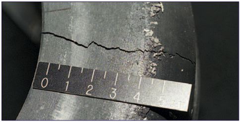
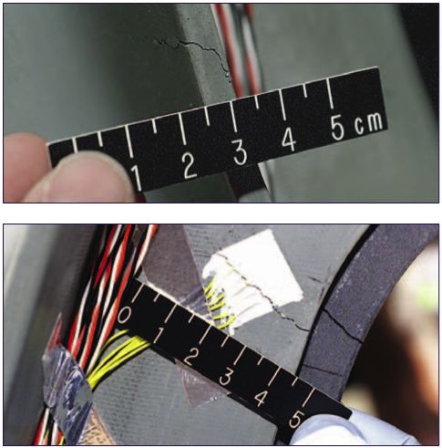
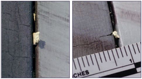
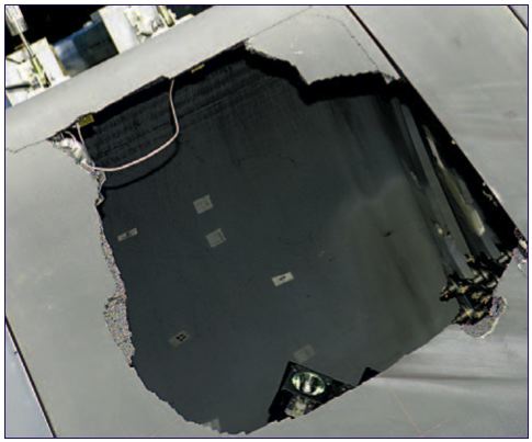
A primary concern of investigators was that external loads present in the flight environment might add substantial extra force to the left wing. However, analysis demonstrated that the only significant external loads on the wing leading edge structural subsystem at about 82 seconds into flight are due to random vibration and the pressure differences inside and outside the leading edge.The Board concluded that the flight environment stresses in the RCC panels and the attachment fittings could be accounted for in post-impact analyses if necessary. However, the dramatic damage produced by the impact tests demonstrated that the foam strike could breach the wing leading edge structure subsystem independent of any stresses associated with the flight environment. (Appendix D.12 contains more detail.)
当初、調査員たちは、左翼への飛行中の外部からの負荷が、衝突時の力にかなり加担していると考えていました。しかし、打ち上げ後82秒の時点で主翼前縁部の構造にかかっていたのは、ランダムな振動と、主翼の内側と外側の気圧差だけでした。調査委員会は、場合によっては、RCCパネルと結合部への飛行中の負荷を考慮したテストをしなければならないと考えていましたが、衝突テストによって生じた驚くほど大きなダメージは、飛行中にかかる負荷がまったくなくても、断熱材衝突だけで十分に主翼前縁部の構造に損傷を与えることができることを示していました。(詳細なデータはAppendics D.12を参照してください)
Test Assembly
テスト環境
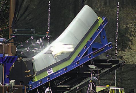
The impact tests were conducted at a Southwest Research Institute facility. Figure 3.8-1 shows the nitrogen gas gun that had evaluated bird strikes on aircraft fuselages. The gun was modified to accept a 35-foot-long rectangular barrel, and the target site was equipped with sensors and high-speed cameras that photographed 2,000 to 7,000 frames per second, with intense light provided by theater spotlights and the sun.
衝突テストは、サウスウエスト研究所の施設を利用して行われました。図3-8-1は航空機の胴体への鳥の衝突をテストするための窒素ガスガンです。このガスガンは35フィートの四角い銃身を使えるように改造され、ターゲットの部分にはセンサーと一秒間に2000コマから7000コマ撮影できるハイスピードカメラが設置されました。また、照明には劇場用のスポットライトと、太陽の光が利用されました。
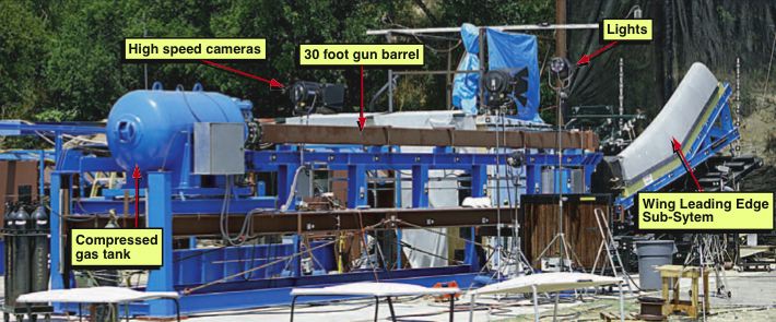
Figure 3.8-1. Nitrogen-powered gun at the Southwest Research Institute used for the test series.
Figure 3.8-1. テストに使われたサウスウエスト研究所の窒素ガスガン
Test Impact Target
ターゲット
The leading edge structural subsystem test target was designed to accommodate the Boards evolving determination of the most likely point of impact. Initially, analysis pointed to the main landing gear door. As the imaging and transport teams refined their assessments, the likely strike zone narrowed to RCC panels 6 through 9. Because of the long lead time to develop and produce the large complex test assemblies, investigators developed an adaptable test assembly (Figure 3.8-2) that would provide a structurally similar mounting for RCC panel assemblies 5 to 10 and would accommodate some 200 sensors, including high-speed cameras, strain and deflection gauges, accelerometers, and load cells.14
テスト用のターゲットである主翼前縁部の構造物は、最も衝突が起きた可能性が一番高い場所を特定するための材料を調査委員会に提供するために作られました。当初分析の対象とされたのは主着陸脚のドアでしたが、画像・軌道分析チームの調査結果により、衝突が起きた可能性のある場所はRCCパネルの6番から9番までの部分に狭められました。制作の準備に必要な時間を短縮し、巨大で複雑なテストシステムを構築するのを避けるために、調査員は汎用性の高いテスト環境を開発しました(図3-8-2)。このシステムには、ハイスピードカメラ、応力ゲージ、たわみゲージ、加速度計、圧力センサーなどを含む、200個もののセンサーが取り付けられました。
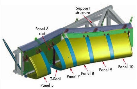
Figure 3.8-2. Test assembly that provided a structural mounting for RCC panel assemblies 5 to 10 and would accommodate some 200 sensors and other test equipment.
Figure 3.8-2. 5番から10番までのRCCパネル、200を超えるセンサー、各種のテスト用機器からなるテスト用ターゲット。
Test Panels
テスト用RCCパネル
RCC panels 6 and 9, which bracketed the likely impact region, were the first identified for testing. They would also permit a comparison of the structural response of panels with and without the additional thickness at certain locations.
断熱材が衝突したと見られる位置の左右に取り付けられていた6番と9番RCCパネルが最初にテスト候補として挙げられ、それらに対して特定の位置の厚みを変えて構造的な変化を比較しました。
Panel 6 tests demonstrated the complex system response to impacts. While the initial focus of the investigation had been on single panel response, early results from the tests with fiberglass panels hinted at "boundary condition" effects. Instruments measured high stresses through panels 6, 7, and 8. With this in mind, as well as forensic and sensor evidence that panel 8 was the likeliest location of the foam strike, the Board decided that the second RCC test should target panel 8, which was placed in an assembly that included RCC panels 9 and 10 to provide high fidelity boundary conditions. The decision to impact test RCC panel 8 was complicated by the lack of spare RCC components.
6番パネルへのテストは複雑なシステムが衝突にどのような反応をするかを示していました。当初、調査は単体のパネルの反応に焦点を当てていましたが、初期のテストの結果は、これらのファイバーグラスのパネルの「境界条件」効果を暗示していたのです。計測機器は6番、7番、8番のパネルに強いストレスが掛かったことを示していました。これを念頭に置き、断熱材の衝突箇所が8番パネルである可能性が高いという科学的調査やセンサーの値が示す結果を踏まえ、調査委員会は2回目の衝突テストを境界条件を忠実に再現するために9番と10番パネルと一緒にマウントされた8番パネルに対して行うことを決定しました。8番パネルへの衝突テストはスペアのRCCパネルが無いことから難しい決断となりました。
The specific RCC panel assemblies selected for testing had flight histories similar to that of STS-107, which was Columbias 28th flight. Panel 6 had flown 30 missions on Discovery, and Panel 8 had flown 26 missions on Atlantis.
テストに使うRCCパネルの選択は、コロンビアの28回目の飛行であったSTS-107と同じようなフライト数を持つパネルが選ばれました。6番パネルはディスカバリーによって30回使われたもの、8番パネルはアトランティスによって26回使われたものです。
Test Projectile
Test Projectile
The preparation of BX-250 foam test projectiles used the same material and preparation processes that produced the foam bipod ramp. Foam was selected as the projectile material because foam was the most likely debris, and materials other than foam would represent a greater threat. The testing required a projectile (see Figure 3.8-3) made from standard stock, so investigators selected a rectangular cross-section of 11.5 by 5.5 inches, which was within 15 percent of the footprint of the mean debris size initially estimated by image analysis. To account for the foams density, the projectile length was cut to weigh 1.67 pounds, a figure determined by image and transport analysis to best represent the STS-107 projectile. For foam with a density of 2.4 pounds per cubic foot,15 the projectile dimensions were 19 inches by 11.5 inches by 5.5 inches.
BX-250 断熱材のテスト用射出体は、バイポッドランプの断熱材を製造するのと同じプロセスで作られました。射出体として断熱材が選択されたのは、それが衝突した破片である可能性が最も高かったこと、また衝突した可能性があるもののうち、断熱材が最も危険性が低い物体だったからです。
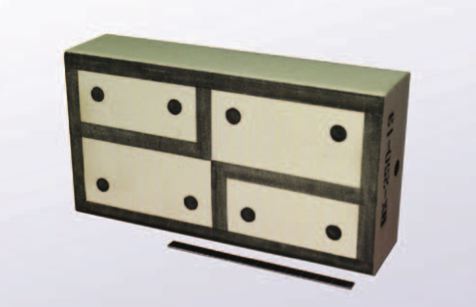
Figure 3.8-3. A typical foam projectile, which has marks for determining position and velocity as well as blackened outlines for indicating the impact footprint.
Figure 3.8-3. A typical foam projectile, which has marks for determining position and velocity as well as blackened outlines for indicating the impact footprint.
Impact Angles
The precise impact location of the foam determined the impact angle because the debris was moving almost parallel to the Orbiters fuselage at impact. Tile areas would have been hit at very small angles (approximately five degrees), but the curvature of the leading edge created angles closer to 20 degrees (see Figure 3.4-4).
The foam that struck Columbia on January 16, 2003, had both a translational speed and a rotational speed relative to the Orbiter. The translational velocity was easily replicated by adjusting the gas pressure in the gun. The rotational energy could be calculated, but the impact force depends on the material composition and properties of the impacting body and how the rotating body struck the wing. Because the details of the foam contact were not available from any visual evidence, analysis estimated the increase in impact energy that would be imparted by the rotation. These analyses resulted in a three-degree increase in the angle at which the foam test projectile would hit the test panel.16
The "clocking angle" was an additional consideration. As shown in Figure 3.8-4, the gun barrel could be rotated to change the impact point of the foam projectile on the leading edge. Investigators conducted experiments to determine if the corner of the foam block or the full edge would impart a greater force. During the fiberglass tests, it was found that a clocking angle of 30 degrees allowed the 11.5-inch-edge to fully contact the panel at impact, resulting in a greater local force than a zero degree angle, which was achieved with the barrel aligned vertically. A zero-degree angle was used for the test on RCC panel 6, and a 30-degree angle was used for RCC panel 8.
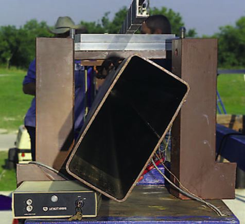
Figure 3.8-4. The barrel on the nitrogen gun could be rotated to adjust the impact point of the foam projectile.
Figure 3.8-4. The barrel on the nitrogen gun could be rotated to adjust the impact point of the foam projectile.
Five engineering tests on fiberglass panels (see Figure 3.8-5) established the test parameters of the impact tests on RCC panels. Details of the fiberglass tests are inAppendix D.12.