3.2 THE EXTERNAL TANK AND FOAM
3.2 The External Tank and Foam
ー外部燃料タンクおよび断熱材ー
ー外部燃料タンクおよび断熱材ー
The External Tank is the largest element of the Space Shuttle. Because it is the common element to which the Solid Rocket Boosters and the Orbiter are connected, it serves as the main structural component during assembly, launch, and ascent. It also fulfills the role of the low-temperature, or cryogenic, propellant tank for the Space Shuttle Main Engines. It holds 143,351 gallons of liquid oxygen at minus 297 degrees Fahrenheit in its forward (upper) tank and 385,265 gallons of liquid hydrogen at minus 423 degrees Fahrenheit in its aft (lower) tank. #1
外部燃料タンクは、スペースシャトルを構成する最も大きな部分です。固体燃料ロケットとオービターを接続し、組み立て時や打ち上げ、上昇の際に機体の主要な構造を支え、また、スペースシャトルの主エンジンの低温ないし極低温の燃料を充填した燃料タンクとしての役割を果たします。前方(上部)のタンクに華氏マイナス297度の液体酸素を143,351ガロン、後部(下部)のタンクに華氏マイナス423度の液体水素を385,265ガロン保持しています。
Lockheed Martin builds the External Tank under contract to the NASA Marshall Space Flight Center at the Michoud Assembly Facility in eastern New Orleans, Louisiana.
外部燃料タンクはNASAマーシャル宇宙飛行センターとの契約の元、ロッキードマーティン社によって、ルイジアナ州ニューオルリーンズのミショー組立工場で製作されます。
The External Tank is constructed primarily of aluminum al- loys (mainly 2219 aluminum alloy for standard-weight and lightweight tanks, and 2195 Aluminum-Lithium alloy for super-lightweight tanks), with steel and titanium fittings and attach points, and some composite materials in fairings and access panels. The External Tank is 153.8 feet long and 27.6 feet in diameter, and comprises three major sections: the liq- uid oxygen tank, the liquid hydrogen tank, and the intertank area between them(see Figure 3.2-1).The liquid oxygen and liquid hydrogen tanks are welded assemblies of machined and formed panels, barrel sections, ring frames, and dome and ogive sections.The liquid oxygen tank is pressure-tested with water,and the liquid hydrogen tank with compressed air, before they are incorporated into the External Tank assembly. STS-107 used Lightweight External Tank-93.
外部燃料タンクは主としてアルミニウム合金(標準タンクおよび軽量タンクは2219アルミニウム合金、超軽量タンクは2195アルミニウム-リチウム合金)からなり、接続部や結合金具には鉄やチタンが、フェアリングやアクセスパネルには複合材料が使われています。全長が153.8フィート、直径は27.6フィートあり、液体酸素タンク、液体水素タンク、そしてこれらの間にある中間タンクの3つの主要なセクションからなります(図3-2-1)。液体酸素と液体水素タンクは機械加工され整形された、パネルや円筒形の部分、リング状のフレーム、ドーム状の部分をを溶接によってつなぎ合わせて作られます。外部燃料タンクとして1つに組み立てられる前に、液体酸素タンクは水で、液体水素タンクは圧縮空気によって圧力テストが行われます。STS-107では、軽量外部燃料タンク-93が使用されました。
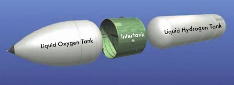
Figure 3.2-1. The major components of the External Tank. Liquid Oxygen Tank Liquid Hydrogen Tank Intertank
図3-2-1 : 外部燃料タンクの主要なコンポーネント。液体酸素タンク、液体水素タンク、中間タンク。
The propellant tanks are connected by the intertank, a 22.5- foot-long hollow cylinder made of eight stiffened aluminum alloy panels bolted together along longitudinal joints.Two of these panels, the integrally stiffened thrust panels (so called because they react to the Solid Rocket Booster thrust loads) are located on the sides of the External Tank where the Solid Rocket Boosters are mounted; they consist of single slabs of aluminum alloy machined into panels with solid longitudinal ribs. The thrust panels are joined across the inner diameter by the intertank truss, the major structural element of the External Tank. During propellant loading, nitrogen is used to purge the intertank to prevent condensation and also to pre- vent liquid oxygen and liquid hydrogen from combining.
それぞれの燃料タンクは中間タンク―全長22.5フィート、8つの補強されたアルミニウム合金製のパネルを縦方向のジョイントでボルト止めした中空のシリンダー―で接続されます。 これらのうち2つのパネルは、外部燃料タンクの側面、固体燃料ロケットブースターが接続されている部分に位置する、一体補強されたスラストパネル(固体燃料ロケットブースターの推力[スラスト]の負荷に反応するためにこう呼ばれます)です。これらのパネルはアルミニウムのスラブから削りだされ、縦方向に固いリブが通っています。二枚のスラストパネルはインタータンクトラス―外部燃料タンクの主要構造―によって直径方向で接続されています。燃料が充填されている間は、インタータンクは窒素によってパージされます。これは結露を防ぎ、また液体酸素と液体水素が混じり合うのを防ぐためです。
The External Tank is attached to the Solid Rocket Boosters by bolts and fittings on the thrust panels and near the aft end of the liquid hydrogentank.The Orbiter is attached to the External Tank by two umbilical fittings at the bottom (that also contain fluid and electrical connections) and by a "bipod" at the top. The bipod is attached to the External Tank by fittings at the right and left of the External Tank center line.The bipod fittings, which are titanium forgings bolted to the External Tank, are forward (above) of the intertank-liquid hydrogen flange joint (see Figures 3.2-2 and 3.2-3). Each forging con- tains a spindle that attaches to one end of a bipod strut and rotates to compensate for External Tank shrinkage during the loading of cryogenic propellants.
外部燃料タンクはスラストパネル上と液体水素タンクの最後部で固体燃料ロケットにボルトと接合金具で接続されています。オービターはタンクの底の供給管部の接合金具(この部分には液体と電気を通すための接続も含まれています)と先端部の「バイポッド」で接続されています。バイポッドは外部燃料タンクに中心軸をはさんで左右の接合金具で接続されています。このバイポッドの接合金具はチタンの鍛造品で外部燃料タンクの前方(上部)、インタータンクと液体酸素タンクの間のフランジジョイントにボルト止めされています(図3-2-2、図3-2-3)。これらの鍛造品には片方の端をバイポッドストラットに接続され、極低温の燃料を充填する際の外部燃料タンクの収縮を補正するスピンドルが付けられています。
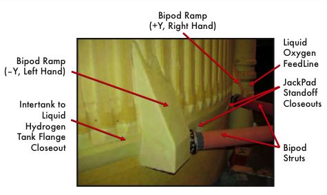
Figure 3.2-2. The exterior of the left bipod attachment area show- ing the foam ramp that came off during the ascent of STS-107.
図3-2-2 : 左バイポッド接続部分の外観。STS-107の上昇中に破片が脱落した断熱材の傾斜部(ランプ)が見える
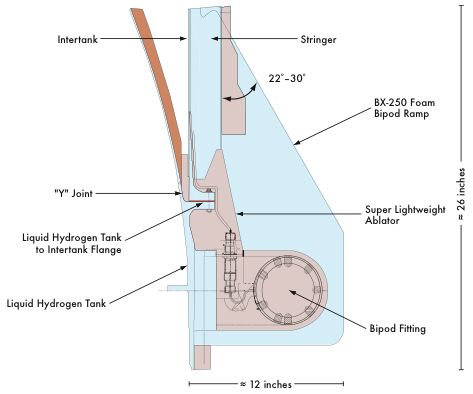
Figure 3.2-3. Cutaway drawing of the bipod ramp and its associated fittings and hardware.
図3-2-3 : バイポッド傾斜部および関連する接合金具とパーツの断面図。.
External Tank Thermal Protection System Materials
外部燃料タンク耐熱システム
The External Tank is coated with two materials that serve as the Thermal Protection System: dense composite ablators for dissipating heat, and low density closed-cell foams for high insulation efficiency.2 (Closed-cell materials consist of small pores filled with air and blowing agents that are separated by thin membranes of the foams polymeric component.) The External Tank Thermal Protection System is designed to maintain an interior temperature that keeps the oxygen and hydrogen in a liquid state, and to maintain the temperature of external parts high enough to prevent ice and frost from forming on the surface. Figure 3.2-4 summarizes the foam systems used on the External Tank for STS-107.
外部燃料タンクは耐熱システムとして、熱を散逸させる高密度の溶融性の複合材料、高い断熱効果を持つ低密度の独立気泡発泡材の二つの物質で覆われています。(独立気泡物質は高分子化合物の泡の膜で隔てられた小さな気泡と膨張剤から出来た物質です。)外部燃料タンク耐熱システムは内部を酸素と水素が液体の状態を保てる温度に、外部のパーツの温度を霜や氷が付着しない程度に高い温度に保つように設計されています。図3-2-4にSTS-107の外部燃料タンクに使用された断熱材システムを示します。
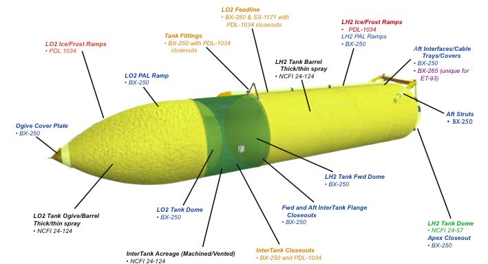
Figure 3.2-4. Locations of the various foam systems as used on ET-93, the External Tank used for STS-107.
図3-2-4 : STS-107で使用された外部燃料タンクET-93に使用された各種の断熱材の場所を示します。
The adhesion between sprayed-on foam insulation and the External Tanks aluminum substrate is actually quite good, provided that the substrate has been properly cleaned and primed. (Poor surface preparation does not appear to have been a problem in the past.) In addition, large areas of the aluminum substrate are usually heated during foam application to ensure that the foam cures properly and develops the maximum adhesive strength. The interface between the foam and the aluminum substrate experiences stresses due to differences in how much the aluminum and the foam contract when subjected to cryogenic temperatures, and due to the stresses on the External Tanks aluminum structure while it serves as the backbone of the Shuttle stack. While these stresses at the foam-aluminum interface are certainly not trivial, they do not appear to be excessive, since very few of the observed foam loss events indicated that the foam was lost down to the primed aluminum substrate.
吹き付けられた断熱材と外部燃料タンクのアルミの素地の間の接着は非常に強力で、下地は丁寧に洗浄され調整されています。(これまで下地処理の質が低いことが原因となって問題が発生したことはありません。)さらに、断熱材を付加する際、アルミニウムの下地の大半の部分が暖められ、断熱材が適切に硬化し最大の接着力を発揮するように処理されています。断熱材とアルミニウムの下地の間には、低温にさらされた時のアルミと断熱材の収縮の差によって負荷がかかります。さらに、外部燃料タンクのアルミの構造部分がシャトルの背骨としての役割を果たしているために、これによっても断熱材とアルミの下地の間に負荷がかかります。この発泡剤とアルミニウムの境界での負荷がさほど大きくなく、目立った影響も見られなかったにもかかわらず、ごく僅かながら断熱材の脱落が観察されており、アルミニウムの下地から断熱材がはがれ落ちていたことを示しています。
Throughout the history of the External Tank, factors unrelated to the insulation process have caused foam chemistry changes (Environmental Protection Agency regulations and material availability, for example). The most recent changes resulted from modifications to governmental regulations of chlorofluorocarbons.
これまで、外部燃料タンクが使用されてきたなかで、断熱材の処理行程とは関係のない理由で、その化学組成が変えられたことがありました。(例えば、環境保護局の規制や、材料の入手などの理由です。)直近の変更は、フロンガスに関する政府の規制を受けてのものです。
Most of the External Tank is insulated with three types of spray-on foam. NCFI 24-124, a polyisocyanurate foam ap- plied with blowing agent HCFC 141b hydrochlorofluorocarbon, is used on most areas of the liquid oxygen and liquid hydrogen tanks. NCFI 24-57, another polyisocyanurate foam applied with blowing agent HCFC 141b hydrochlo- rofluorocarbon, is used on the lower liquid hydrogen tank dome. BX-250, a polyurethane foam applied with CFC-11 chlorofluorocarbon, was used on domes, ramps, and areas where the foam is applied by hand. The foam types changed on External Tanks built after External Tank 93, which was used on STS-107, but these changes are beyond the scope of this section.
外部燃料タンクの大半の部分には、3種類の吹き付け用の断熱材が使われています。液体酸素および液体水素タンクの大半の部分に使われているNCFI24-124はポリイソシアヌレートの断熱材で、HCFC 141b炭化クロロフルオロカーボンが膨張剤として使われています。液体水素タンクの下部ドームに使われるNCFI 24-57は別のポリイソシアヌレートの断熱材でこれも、HCFC 141b炭化クロロフルオロカーボンが膨張剤として使われています。BX-250はポリウレタンの断熱材で、CFC-11クロロフルオロカーボンとともに使われ、ドームや傾斜部、手作業で断熱材が付加される部分に使用されます。STS-107で使用された外部燃料タンク93以後のタンクでは断熱材が変更されましたが、この変更の内容についてはこの章では扱いません。
Metallic sections of the External Tank that will be insulated with foam are first coated with an epoxy primer. In some areas, such as on the bipod hand-sculpted regions, foam is applied directly over ablator materials. Where foam is ap- plied over cured or dried foam, a bonding enhancer called Conathane is first applied to aid the adhesion between the two foam coats.
断熱材とともに付加される外部燃料タンクの金属部分は、エポキシ樹脂でコーティングされています。手作業で整形されるバイポッド部分などの一部の箇所では、融蝕性材料の上に直接断熱材が付加されます。断熱材が既に乾燥するか硬化した場所にさらに断熱材が追加される場合には、両方の断熱材のコーティングを接着するためにまずConathaneと呼ばれる接着強化剤が塗布されます。
After foam is applied in the intertank region, the larger areas of foam coverage are machined down to a thickness of about an inch. Since controlling weight is a major concern for the External Tank, this machining serves to reduce foam thickness while still maintaining sufficient insulation.
インタータンク部分への付加が終わった後、断熱材は広範囲に渡って1インチの厚さに加工されます。外部燃料タンクの重量の軽減は重要性が高く、この機械加工によって断熱材は必要最小限の厚さにされるのです。
The insulated region where the bipod struts attach to the External Tank is structurally, geometrically, and materially complex. Because of concerns that foam applied over the fittings would not provide enough protection from the high heating of exposed surfaces during ascent, the bipod fittings are coated with ablators. BX-250 foam is sprayed by hand over the fittings (and ablator materials), allowed to dry, and manually shaved into a ramp shape. The foam is visually inspected at the Michoud Assembly Facility and also at the Kennedy Space Center, but no other non-destructive evaluation is performed.
外部燃料タンクとバイポッド部の支柱が接続される部分は構造的にも、幾何学的にも、また材料の面でも複雑な箇所です。これらの金具部分に付加された断熱材は、上昇中の高熱に対して十分な保護ができない可能性があるため、融蝕性材料が塗布されているのです。BX-250断熱材は金具や融蝕性材料の上に手作業で吹き付けられ、乾燥されて、手作業で傾斜部の形に削られます。断熱材はミショー組立工場とケネディ宇宙センターで目視で点検されますが、それ以外の非破壊検査は行われていませんでした。
Since the Shuttles inaugural flight, the shape of the bipod ramp has changed twice. The bipod foam ramps on External Tanks 1 through 13 originally had a 45-degree ramp angle. On STS-7, foam was lost from the External Tank bipod ramp; subsequent wind tunnel testing showed that shallower angles were aerodynamically preferable. The ramp angle was changed from 45 degrees to between 22 and 30 degrees on External Tank 14 and later tanks. A slight modification to the ramp impingement profile, implemented on External Tank 76 and later, was the last ramp geometry change.
シャトルの最初の飛行以来、バイポッド傾斜部の形状は2回変更されています。外部燃料タンク1〜13までのバイポッドの断熱材傾斜部の角度は45度でした。しかし、STS-7においてバイポッド傾斜部からの断熱材の脱落が起き、その後の風洞テストでより浅い角度の方が空気力学的に望ましいという結果が出ました。そのため、外部燃料タンク14以降、傾斜部の角度は45度から22度ないし30度に変更されたのです。さらに、外部燃料タンク76以後、傾斜部の衝撃特性が若干変更されました。これが傾斜部の形状に加えられた最後の変更です。
STS-107 Left Bipod Foam Ramp Loss
STS-107 左バイポッド傾斜部断熱材の脱落
A combination of factors, rather than a single factor, led to the loss of the left bipod foam ramp during the ascent of STS-107. NASA personnel believe that testing conducted during the investigation, including the dissection of as-built hardware and testing of simulated defects, showed conclusively that pre-existing defects in the foam were a major factor, and in briefings to the Board, these were cited as a necessary condi- tion for foam loss. However, analysis indicated that pre-ex- isting defects alone were not responsible for foam loss.
STS-107の上昇中に起きた左バイボッド傾斜部の断熱材の脱落には1つではなく複数の原因が考えられます。NASAの職員たちは、調査の過程で行われた既存のハードウエアの分析と不具合があった場合のシミュレーションなどのテストの結果から、そもそも断熱材に不具合があったことが主要な原因であると考え、事故調査委員会への説明の中で、断熱材の脱落の条件として提示しました。しかし、分析結果は断熱材の不具合だけでは脱落が起きないことを示していました。
The basic External Tank was designed more than 30 years ago. The design process then was substantially different than it is today. In the 1970s, engineers often developed particular facets of a design (structural, thermal, and so on) one after another and in relative isolation from other engineers working on different facets. Today, engineers usually work together on all aspects of a design as an integrated team. The bipod fitting was designed first from a structural stand- point, and the application processes for foam (to prevent ice formation) and Super Lightweight Ablator (to protect from high heating) were developed separately. Unfortunately, the structurally optimum fitting design, along with the geometric complexity of its location (near the flange between the in- tertank and the liquid hydrogen tank), posed many problems in the application of foam and Super Lightweight Ablator that would lead to foam-ramp defects.
外部燃料タンクの設計は30年以上前のものです。当時の設計のプロセスは現在と全く異なっていました。1970年代のエンジニア達は一人一人が全体の設計の特定の部分(構造、熱、などです)だけを担当し、他の部分を担当しているエンジニアからは比較的孤立していました。現在は、多くの場合エンジニア達は1つのチームとして設計のあらゆる側面に対して共同して作業を行います。バイポッド部の結合金具は構造的な側面から設計され、(氷の形成を防ぐための)断熱材の付加や(高熱から保護するための)超軽量融蝕性材料の開発などは別々に行われました。不幸なことに、この部分の複雑な形状(これは、インタータンクと液体水素タンクの間のフランジに近いためです)に従って構造的に最適な設計が優先されたために、傾斜部の不具合の原因となる断熱材や超軽量融蝕性材料の付加に関わる数多くの問題が出てきたのです。
Although there is no evidence that substandard methods were used to qualify the bipod ramp design, tests made near- ly three decades ago were rudimentary by todays standards and capabilities. Also, testing did not follow the often-used engineering and design philosophy of "Fly what you test and test what you fly." Wind tunnel tests observed the aerodynamics and strength of two geometries of foam bipod enclosures (flat-faced and a 20-degree ramp), but these tests were done on essentially solid foam blocks that were not sprayed onto the complex bipod fitting geometry. Extensive material property tests gauged the strength, insulating potential, and ablative characteristics of foam and Super Lightweight Ablator specimens.
バイポッド傾斜部の設計を決定するにあたり、低水準の方法がとられていた形跡はありませんが、約30年前に行われていたテストは現在のそれに比べて水準も能力的にも劣ったものでした。また、テストはエンジニアリングや設計において標準的な「テストしたものを飛ばし、飛ばしたものをテストする」というポリシーに従っていませんでした。バイポッドの囲いの断熱材の2種類の形状(直角のものと20度のもの)に関する空力特性と強度を調べる風洞テストが行われましたが、これらのテストは断熱材の固まりに対して行われ、バイポッドの接合金具の複雑な形状に断熱材が吹き付けられたものに対するものではありませんでした。また断熱材や超軽量融蝕性材料の試料に対して、広範囲に渡る材料特性のテストが行われ、断熱材と強度や耐熱性、融蝕性能などが計測されました。
It was - and still is - impossible to conduct a ground-based, simultaneous, full-scale simulation of the combination of loads, airflows, temperatures, pressures, vibration, and acoustics the External Tank experiences during launch and ascent. Therefore, the qualification testing did not truly reflect the combination of factors the bipod would experience during flight. Engineers and designers used the best meth- ods available at the time: test the bipod and foam under as many severe combinations as could be simulated and then interpolate the results. Various analyses determined stresses, thermal gradients, air loads, and other conditions that could not be obtained through testing.
当時も今も、外部燃料タンクが打ち上げ時と上昇中にさらされる負荷や空気の流れ、温度、圧力、振動、音響などについて、地表でフルスケールのシミュレーションを行うことは不可能です。そのため評価テストは本当の意味でバイポッド傾斜部が飛行中にさらされる一連の状況を反映したものではありませんでした。エンジニアや設計者達はその時々で最良の手法を用いてきました。バイポッドや断熱材に対して可能な限り多くの困難な条件の組み合わせの元でシミュレーションを行い、その結果を積み上げてきたのです。ストレスや熱の変化、空気抵抗など、テストから得られない条件は様々な分析によって割り出されたものです。
Significant analytical advancements have been made since the External Tank was first conceived, particularly in computational fluid dynamics (see Figure 3.2-5). Computational fluid dynamics comprises a computer-generated model that represents a system or device and uses fluid-flow physics and software to create predictions of flow behavior, and stress or deformation of solid structures. However, analysis must always be verified by test and/or flight data. The External Tank and the bipod ramp were not tested in the complex flight environment, nor were fully instrumented External Tanks ever launched to gather data for verifying analytical tools. The accuracy of the analytical tools used to simulate the External Tank and bipod ramp were verified only by using flight and test data from other Space Shuttle regions.
外部燃料タンクが最初に計画されて以来、分析手法はめざましい発達を見せました。特に計算流体力学の分野は大きく進歩しています(図:3-2-5)。計算流体力学はコンピューターによって作り出されるシステムや機器のモデル、流体の挙動に関する物理学、そして流体の挙動や構造へのストレスないし変形を予測するソフトウェアなどから構成されます。ただし、これによる分析は常に必ずテストかフライトデータ、あるいはその両方によって検証されなければなりません。外部燃料タンクとバイポッド傾斜部は複雑な飛行状態でのテストは行われませんでしたし、分析ツールの結果を確かめるためのデータを収集するためにすべての機器を備えた状態の外部燃料タンクが打ち上げられたこともありませんでした。外部燃料タンクとバイポッド傾斜部をシミュレートするために使われた分析ツールの精度は、他のスペースシャトルのフライトデータやテストデータに依拠しています。
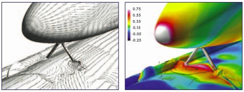
Figure 3.2-5. Computational Fluid Dynamics was used to under- stand the complex flow fields and pressure coefficients around bipod strut. The flight conditions shown here approximate those present when the left bipod foam ramp was lost from External Tank 93 at Mach 2.46 at a 2.08-degree angle of attack.
図3-2-5 : 複雑な空気の流れやバイポッド支柱周辺の圧力計数を把握するために計算流体力学が使われました。ここでは、おおよそ左バイポッド傾斜部から断熱材が脱落した時点,マッハ2.46、迎え角2.08度での外部燃料タンク93の飛行中の状態が示されています。
Further complicating this problem, foam does not have the same properties in all directions, and there is also variability in the foam itself. Because it consists of small hollow cells, it does not have the same composition at every point. This combination of properties and composition makes foam extremely difficult to model analytically or to characterize physically. The great variability in its properties makes for difficulty in predicting its response in even relatively static conditions, much less during the launch and ascent of the Shuttle. And too little effort went into understanding the origins of this variability and its failure modes.
さらに問題を複雑にしているのは、断熱材が方向によって異なる性質を持っているうえに、断熱材そのものの性質も変化しやすいということです。これは、断熱材が小さな中空の気泡からできていて、場所によって組成が違ってしまうためです。この両者の性質と組成が、断熱材をモデル化して分析したり物理的な特性を定めることを非常に困難にしているのです。この非常に幅広い特性のために静的な環境でさえ挙動を予測することが難しく、ましてシャトルの打ち上げ時や上昇時はさらに困難を極めます。また、その変化のしやすさの理由と故障モードを理解するための努力はこれまで行われていませんでした。
The way the foam was produced and applied, particularly in the bipod region, also contributed to its variability. Foam consists of two chemical components that must be mixed in an exact ratio and is then sprayed according to strict specifications. Foam is applied to the bipod fitting by hand to make the foam ramp, and this process may be the primary source of foam variability. Board-directed dissection of foam ramps has revealed that defects (voids, pockets, and debris) are likely due to a lack of control of various combinations of parameters in spray-by-hand applications, which is exacerbated by the complexity of the underlying hardware configuration. These defects often occur along "knit lines," the boundaries between each layer that are formed by the repeated application of thin layers - a detail of the spray-by- hand process that contributes to foam variability, suggesting that while foam is sprayed according to approved proce- dures, these procedures may be questionable if the people who devised them did not have a sufficient understanding of the properties of the foam.
特にこのバイポッド近辺については、断熱材が製造、付加される方法もこの可変性の一因となっています。断熱材は二種類の化学成分を含んでおり、正確な比率で混ぜ合わされる必要があり、吹き付ける方法も厳密に定められています。バイポッド接続部への断熱材の付加、傾斜部の形成は手作業で行われており、これが可変性の主原因となっています。事故調査委員会が主導で行ったバイポッド接続部の分解調査では、手作業で付加作業が行われることでそれぞれの要素に対するコントロールが失われ、いくつもの不具合(空隙やくぼみ、破片など)が起きていることが明らかになりました。さらに、この部分の機器の構成の複雑さがこれに拍車をかけていたのです。これらの不具合は、「ニットライン」と呼ばれるでしばしば起きていました。ニットラインとは、断熱材の質のばらつきの一因となった手作業での吹き付け作業によって、繰り返し薄いレイヤー状に断熱材が塗布されたことで生じた、それぞれのレイヤーの境界の部分です。これが示唆するのは、断熱材は規定の手順に従って塗布されていたにもかかわらず、作業をした人々が断熱材の性質に対する適切な知識を持っていなかったとすれば、この手順そのものに疑問がもたれるということです。
Subsurface defects can be detected only by cutting away the foam to examine the interior. Non-destructive evaluation techniques for determining External Tank foam strength have not been perfected or qualified (although non-destruc- tive testing has been used successfully on the foam on Boeings new Delta IV booster, a design of much simpler geometry than the External Tank). Therefore, it has been impossible to determine the quality of foam bipod ramp sonany External Tank. Furthermore, multiple defects in some cases can combine to weaken the foam along a line or plane.
表面下の不具合は内部を確認するために断熱材を切り取ることでしか発見することができません。外部燃料タンクの断熱材の強度を計測するための非破壊検査の手法は未だ完全なものではなく、承認されていません(ただし、外部燃料タンクよりシンプルな形状をしているボーイング社の新しいデルタIVブースターでは非破壊検査の導入はうまくいっています)。そのため、バイポッド傾斜部の断熱材のクオリティを測定する方法が無かったのです。そのうえ、あるケースでは複数の不具合部分が重なり、ライン状ないし面状に断熱材の強度を下げていたことが分かりました。
"Cryopumping" has long been theorized as one of the processes contributing to foam loss from larger areas of coverage. If there are cracks in the foam, and if these cracks lead through the foam to voids at or near the surface of the liquid oxygen and liquid hydrogen tanks, then air, chilled by the extremely low temperatures of the cryogenic tanks, can liquefy in the voids. After launch, as propellant levels fall and aerodynamic heating of the exterior increases, the temperature of the trapped air can increase, leading to boiling and evaporation of the liquid, with concurrent buildup of pressure within the foam. It was believed that the resulting rapid increase in subsurface pressure could cause foam to break away from the External Tank.
「クライオポンピング」は、広範囲におよぶ断熱材の脱落のプロセスの1つとして理論化されてきました。もし、断熱材に亀裂が生じ、その亀裂が液体酸素ないし液体水素近くの気泡に達していたとすると、極低温のタンクによって極度に冷やされた空気はその気泡の中で液化することになります。打ち上げ後、燃料の水位が下がり、空力的な加熱によって外部の温度が上昇することで、気泡に捉えられた液体の空気の温度が上がり、沸騰と気化が起こります。これによって断熱材内部の圧力が増すことになるのです。このような表面化での圧力の急激な上昇は、外部燃料タンクからの断熱材の脱落を引き起こすと考えられてきました。
"Cryoingestion" follows essentially the same scenario, except it involves gaseous nitrogen seeping out of the in- tertank and liquefying inside a foam void or collecting in the Super Lightweight Ablator. (The intertank is filled with nitrogen during tanking operations to prevent condensation and also to prevent liquid hydrogen and liquid oxygen from combining.) Liquefying would most likely occur in the circumferential "Y" joint, where the liquid hydrogen tank mates with the intertank, just above the liquid hydrogen-in- tertank flange. The bipod foam ramps straddle this complex feature. If pooled liquid nitrogen contacts the liquid hydro- gen tank, it can solidify, because the freezing temperature of liquid nitrogen (minus 348 degrees Fahrenheit) is higher than the temperature of liquid hydrogen (minus 423 degrees Fahrenheit). As with cryopumping, cryoingested liquid or solid nitrogen could also "flash evaporate" during launch and ascent, causing the foam to crack off. Several paths allow gaseous nitrogen to escape from the intertank, including beneath the flange, between the intertank panels, through the rivet holes that connect stringers to intertank panels, and through vent holes beneath the stringers that prevent over- pressurization of the stringers.
「クライオインジェスチョン」は、クライオポンピングとほぼ同じシナリオをたどりますが、中間タンクから漏れだした窒素ガスが断熱材中の気泡の中で液化するか、超軽量融蝕性材料内で集中するという点が違っています。(中間タンクには、燃料が充填される際、結露と液体水素と液体酸素が混じり合うのを防ぐために窒素が満たされます)液化は特に液体水素タンクが中間タンクと接する部分、液体水素と中間タンクのフランジ付近のYジョイントの周辺でおこりやすくなります。バイポッド傾斜部は、まさしくこの複雑な部分をまたぐように設置されているのです。液体窒素の凝固点(華氏マイナス348度)は液体水素の温度(華氏マイナス423度)より高いため、もし液体の窒素が液体水素タンクに触れたとすれば固化するはずです。クライオボンピングと同じように、クライオインジェスチョンにおいても、液体もしくは個体の窒素は打ち上げと上昇中の際に「瞬間蒸発」を起こし、断熱材の亀裂と脱落を引き起こすでしょう。中間タンクから窒素ガスが漏れだすルートは複数考えられます。フランジの下、中間タンクのパネルの間、梁を中間タンクのパネルに止めているリベットの孔、梁に圧力がかかりすぎるのを防ぐための梁の下の排気口などです。
No evidence suggests that defects or cryo-effects alone caused the loss of the left bipod foam ramp from the STS-107 External Tank. Indeed, NASA calculations have suggested that during ascent, the Super Lightweight Ablator remains just slightly above the temperature at which nitro- gen liquefies, and that the outer wall of the hydrogen tank near the bipod ramp does not reach the temperature at which nitrogen boils until 150 seconds into the flight,#3 which is too late to explain the only two bipod ramp foam losses whose times during ascent are known. Recent tests at the Marshall Space Flight Center revealed that flight conditions could permit ingestion of nitrogen or air into subsurface foam, but would not permit "flash evaporation" and a sufficient subsurface pressure increase to crack the foam. When conditions are modified to force a flash evaporation, the failure mode in the foam is a crack that provides pressure relief rather than explosive cracking. Therefore, the flight environment itself must also have played a role. Aerody- namic loads, thermal and vacuum effects, vibrations, stress in the External Tank structure, and myriad other conditions may have contributed to the growth of subsurface defects, weakening the foam ramp until it could no longer withstand flight conditions.
これらの不具合や超低温効果が単体でSTS-107の外部燃料タンクの左バイポッド傾斜部の断熱材の脱落を引き起こしたと考える理由はありません。事実、NASAの計算では、上昇中に超軽量融蝕性材によって窒素は液体化するより少し上の温度で保たれ、バイポッド傾斜部付近の液体水素タンクの外壁も飛行開始から150秒間の間は窒素が沸騰するほどには高くなりません。この時間では遅すぎて知られているバイポッド傾斜部の断熱材の脱落のうち説明できるのは2件だけなのです。マーシャル宇宙飛行センターで最近行われたテストでは、飛行状態において窒素ないし空気が断熱材の表面下に吸収されることが分かりましたが、「瞬間蒸発」は起きず、断熱材に亀裂が入ることはないという結果が出ました。仮に「瞬間蒸発」が起きるような状況になったとしても、断熱材の故障モードは、破壊的な亀裂ではなく圧力を開放する方に働くはずです。ゆえに、飛行時の環境そのものも、また一因となったに違いありません。空力学的な負荷、熱や真空による影響、振動、外部燃料タンクの構造部へのストレスなど、無数の要因が総合されて断熱材の表面下での異常を増長し、飛行時の状態に耐えられないほどまでに断熱材の傾斜部を強度を下げたと考えられます。
Conditions in certain combinations during ascent may also have contributed to the loss of the foam ramp, even if in- dividually they were well within design certification limits. These include a wind shear, associated Solid Rocket Booster and Space Shuttle Main Engine responses, and liquid oxygen sloshing in the External Tank.4 Each of these conditions, alone, does not appear to have caused the foam loss, but their contribution to the event in combination is unknown.
上昇中の外部の複合的な環境が傾斜部からの断熱材の脱落をもたらした可能性もあります。たとえそれぞれの要素が設計時に想定された限界内にあったとしても、それらの要素が複合されることで脱落が起きたかもしれません。ウィンドシア(急激な風向の変化)、固体燃料ロケットブースターとスペースシャトル主エンジンの影響、外部燃料タンク内での液体酸素の波打ちなどです。これらの環境は単体では断熱材の脱落を引き起こすことはありませんが、これらが複合して起きたときに何がおこるかはよくわかっていないのです。
Negligence on the part of NASA, Lockheed Martin, or United Space Alliance workers does not appear to have been a factor. There is no evidence of sabotage, either during production or pre-launch. Although a Problem Report was written for a small area of crushed foam near the left bipod (a condi- tion on nearly every flight), this affected only a very small region and does not appear to have contributed to the loss of the ramp (see Chapter 4 for a fuller discussion). Nor does the basic quality of the foam appear to be a concern. Many of the basic components are continually and meticulously tested for quality before they are applied. Finally, despite commonly held perceptions, numerous tests show that moisture absorption and ice formation in the foam appears negligible.
NASA、ロッキード・マーティン、ユナイテッド・スペース・アライアンスの一部の作業員の怠慢が原因ではなさそうです。製造段階でも、打ち上げ前にも破壊工作が行われたという証拠はありません。しかし、問題報告書(Problem Report)には、左バイポッド付近の狭い範囲で断熱材が押し潰されていたことが報告されていますが、これが断熱材の脱落につながったとは考えられません(これについては第4章で扱います)。断熱材の元々の品質にも問題はありませんでした。多くの基本構成要素が、組み立てられる前に継続的かつ細心の注意を払ってテストされています。また、一般の認識とは異なり、非常に多くのテストで断熱材への水分の浸透と氷の形成は無視しうるものであることが分かっています。
Foam loss has occurred on more than 80 percent of the 79 missions for which imagery is available, and foam was lost from the left bipod ramp on nearly 10 percent of missions where the left bipod ramp was visible following External Tank separation. For about 30 percent of all missions, there is no way to determine if foam was lost; these were either night launches, or the External Tank bipod ramp areas were not in view when the images were taken. The External Tank was not designed to be instrumented or recovered after separation, which deprives NASA of physical evidence that could help pinpoint why foam separates from it.
断熱材の脱落は、撮影が可能だった79のミッションのうち80%で起きています。また、左培ポット傾斜部からの断熱材の脱落は、外部燃料タンクの切り離し時に該当部分が撮影できたミッション中10%で起きていました。すべてのミッション中30%のものは、夜間の打ち上げか外部燃料タンクのバイポッド傾斜部がカメラの視界に入らず撮影ができなかったために断熱材の脱落があったかどうか確認する方法がありませんでした。また、外部燃料タンクは分離の後はモニタ用の機器や回収する方法がないため、NASAが断熱材の脱落が起きた原因を特定することができないのです。
The precise reasons why the left bipod foam ramp was lost from the External Tank during STS-107 may never be known. The specific initiating event may likewise remain a mystery. However, it is evident that a combination of variable and pre-existing factors, such as insufficient testing and analysis in the early design stages, resulted in a highly variable and complex foam material, defects induced by an imperfect and variable application, and the results of that imperfect process, as well as severe load, thermal, pressure, vibration, acoustic, and structural launch and ascent conditions.
なぜ、STS-107で外部燃料タンクの左バイポッド傾斜部から断熱材が脱落したかを正確に知ることはできません。また、その引き金となった要因も謎に包まれています。しかし、既存の様々な要因があったことは明らかです。設計の初期段階でのテストや分析の不十分さ、その結果として変化しやすく複雑なものとなった断熱材の材質、不完全で定型化されていない施行がもたらした断熱材の異常、そして、この不完全なプロセスのが生み出したものだけではなく、強い負荷、熱、圧力、振動、音響、そして打ち上げと上昇時の構造の条件などもその要因となったのです。
Findings:
所見:
F3.2-1 NASAdoes not fully understand the mechanisms that cause foam loss on almost all flights from larger areas of foam coverage and from areas that are sculpted by hand.
F3.2-1
NASAはほぼすべてのミッションで起きていた、断熱材が覆う広範囲のエリアおよび手作業によって整形された部分からの断熱材の脱落の原因を完全には理解していない。
NASAはほぼすべてのミッションで起きていた、断熱材が覆う広範囲のエリアおよび手作業によって整形された部分からの断熱材の脱落の原因を完全には理解していない。
F3.2-2 There are no qualified non-destructive evaluation techniques for the as-installed foam to determine the characteristics of the foam before flight.
F3.2-2
既に付加作業を終えた断熱材の性質をフライトの前に計測する非破壊検査は、いかなる承認された手法も存在しない。
既に付加作業を終えた断熱材の性質をフライトの前に計測する非破壊検査は、いかなる承認された手法も存在しない。
F3.2-3 Foam loss from an External Tank is unrelated to the tanks age and to its total pre-launch expo- sure to the elements. Therefore, the foam loss on STS-107 is unrelated to either the age or expo- sure of External Tank 93 before launch.
F3.2-3
外部燃料タンクからの断熱材の脱落は、タンクの寿命や打ち上げ前にさらされた物質とは無関係である。ゆえに、STS-107での断熱材の脱落も、外部燃料タンク93の製造からの期間や打ち上げ前にさらされた物質とは無関係である。
外部燃料タンクからの断熱材の脱落は、タンクの寿命や打ち上げ前にさらされた物質とは無関係である。ゆえに、STS-107での断熱材の脱落も、外部燃料タンク93の製造からの期間や打ち上げ前にさらされた物質とは無関係である。
F3.2-4 The Board found no indications of negligence in the application of the External Tank Thermal Protection System.
F3.2-4
外部燃料タンクの耐熱システムの組み込み作業での過失の形成はない。
外部燃料タンクの耐熱システムの組み込み作業での過失の形成はない。
F3.2-5 The Board found instances of left bipod ramp shedding on launch that NASAwas not aware of, bringing the total known left bipod ramp shed- ding events to 7 out of 72 missions for which im- agery of the launch or External Tank separation is available.
F3.2-5
事故調査委員会は、NASAが気づいていなかった打ち上げ時の左バイポッド傾斜部からの断熱材の脱落を発見した。打ち上げ時ないし外部燃料タンク切り離し時に該当箇所が撮影が可能だった72のミッションのうち7のミッションで左バイポッド傾斜部からの脱落が見られた。
事故調査委員会は、NASAが気づいていなかった打ち上げ時の左バイポッド傾斜部からの断熱材の脱落を発見した。打ち上げ時ないし外部燃料タンク切り離し時に該当箇所が撮影が可能だった72のミッションのうち7のミッションで左バイポッド傾斜部からの脱落が見られた。
F3.2-6
Subsurface defects were found during the dissec- tion of three bipod foam ramps, suggesting that similar defects were likely present in the left bi- pod ramp of External Tank 93 used on STS-107.
Subsurface defects were found during the dissec- tion of three bipod foam ramps, suggesting that similar defects were likely present in the left bi- pod ramp of External Tank 93 used on STS-107.
F3.2-6
バイポッド傾斜部の断熱材の分解を行った際、表面化に異常が発見された。これは、STS-107で使用された外部燃料タンク93の左バイポッド傾斜部でも同じような異常が起きていた可能性があることを示唆している。
バイポッド傾斜部の断熱材の分解を行った際、表面化に異常が発見された。これは、STS-107で使用された外部燃料タンク93の左バイポッド傾斜部でも同じような異常が起きていた可能性があることを示唆している。
F3.2-7
Foam loss occurred on more than 80 percent of the 79 missions for which imagery was available to confirm or rule out foam loss.
Foam loss occurred on more than 80 percent of the 79 missions for which imagery was available to confirm or rule out foam loss.
F3.2-7
確認可能だった79のミッションのうち80%において、断熱材の脱落が起きていた。
確認可能だった79のミッションのうち80%において、断熱材の脱落が起きていた。
F3.2-8
Thirty percent of all missions lacked sufficient imagery to determine if foam had been lost.
Thirty percent of all missions lacked sufficient imagery to determine if foam had been lost.
F3.2-8
すべてのミッションのうち30%のものが撮影が不十分で行われておらず、断熱材の脱落が起きていたことを確かめることができなかった。
すべてのミッションのうち30%のものが撮影が不十分で行われておらず、断熱材の脱落が起きていたことを確かめることができなかった。
F3.2-9
Analysis of numerous separate variables indicated that none could be identified as the sole initiating factor of bipod foam loss. The Board therefore concludes that a combination of several factors resulted in bipod foam loss.
Analysis of numerous separate variables indicated that none could be identified as the sole initiating factor of bipod foam loss. The Board therefore concludes that a combination of several factors resulted in bipod foam loss.
F3.2-9
数多くの個別の変動要素の分析が行われたが、バイポッド断熱材の脱落を引き起こす単独の要因を特定することはできない。ゆえに、事故調査委員会は、複数の要素が複合してバイポッド断熱材の脱落が引き起こされたと結論する。
数多くの個別の変動要素の分析が行われたが、バイポッド断熱材の脱落を引き起こす単独の要因を特定することはできない。ゆえに、事故調査委員会は、複数の要素が複合してバイポッド断熱材の脱落が引き起こされたと結論する。
Recommendation:
勧告:
R3.2-1
Initiate an aggressive program to eliminate all External Tank Thermal Protection System de- bris-shedding at the source with particular em- phasis on the region where the bipod struts attach to the External Tank.
Initiate an aggressive program to eliminate all External Tank Thermal Protection System de- bris-shedding at the source with particular em- phasis on the region where the bipod struts attach to the External Tank.
R3.2-1
すべての外部燃料タンク耐熱システムにおいて、特にバイポッド支柱部分からの破片の脱落を防ぐ積極的なプログラムを開始すること。
すべての外部燃料タンク耐熱システムにおいて、特にバイポッド支柱部分からの破片の脱落を防ぐ積極的なプログラムを開始すること。
FOAM FRACTURE UNDER HYDROSTATIC PRESSURE