3.3 WING LEADING EDGE STRUCTURAL SUBSYSTEM
3.3 Wing Leading Edge Structural Subsystem
ー主翼前縁部構造サブシステム
ー主翼前縁部構造サブシステム
The components of the Orbiters wing leading edge provide the aerodynamic load bearing, structural, and thermal control capability for areas that exceed 2,300 degrees Fahrenheit. Key design requirements included flying 100 missions with minimal refurbishment, maintaining the aluminum wing structure at less than 350 degrees Fahrenheit, withstanding a kinetic energy impact of 0.006 foot-pounds, and the ability to withstand 1.4 times the load ever expected in operation.*5 The requirements specifically stated that the wing leading edge would not need to withstand impact from debris or ice, since these objects would not pose a threat during the launch phase.*6
オービターの主翼前縁部のコンポーネントは、空力学的な負荷に耐え、華氏2,300度を越える温度域で熱や構造をコントロールする能力を持っています。設計上の要件には、最小限の改修で100回のミッションに使用が可能なこと、アルミニウムの主翼構造は最低でも華氏350度に耐えられること、0.006フィートポンドの衝撃に耐えられること、予測される数値の1.4倍の負荷に耐える能力を持っていることが盛り込まれていました。この要件には、主翼前縁部は破片や氷の衝突に耐える必要がないことが明記されていました。これらの物体は打ち上げ中の脅威とはならないはずだったのです。
Reinforced Carbon-Carbon
強化カーボン-カーボン
The development of Reinforced Carbon-Carbon (RCC) as part of the Thermal Protection System was key to meeting the wing leading edge design requirements. Developed by Ling-Temco-Vought (now Lockheed Martin Missiles and Fire Control), RCC is used for the Orbiter nose cap, chin panel, forward External Tank attachment point, and wing leading edge panels and T-seals. RCC is a hard structural material, with reasonable strength across its operational temperature range (minus 250 degrees Fahrenheit to 3,000 degrees). Its low thermal expansion coefficient minimizes thermal shock and thermoelastic stress.
強化カーボン-カーボン(RCC : Reinforced Carbon-Carbon)の開発は耐熱システムの一部として行われ、 主翼前縁部の設計の中心課題となりました。開発はリングテムコボート社(現ロッキードマーティンミサイル&ファイアコントロール社)で行われ、オービターの機種部分のノーズキャップと機種下パネル、外部燃料タンク前部接続部、主翼全エンプのパネル及びT-シールに使用されています。RCCは剛構造の材質で、運用の際に曝される温度(華氏マイナス250度からプラス3000度まで)に耐える能力を持っています。熱による膨張率が低く、熱衝撃(サーマルショック)や熱負荷を低減します。
Each wing leading edge consists of 22 RCC panels (see Figure 3.3-1), numbered from 1 to 22 moving outward on each wing (the nomenclature is "5-left" or "5-right" to differentiate, for example, the two number 5 panels). Because the shape of the wing changes from inboard to outboard, each panel is unique.
左右の主翼はそれぞれ22のRCCパネルからなり、内側から外へ1番から22番までナンバーが振られています(専門的には「左5番(5-left)」「右5番(5-right)」というように呼ばれ、5番パネルは2枚あることになります)。主翼の形状は内側から外側に向けて変化しているために、それぞれのパネルは同じ形のものは1つもありません。
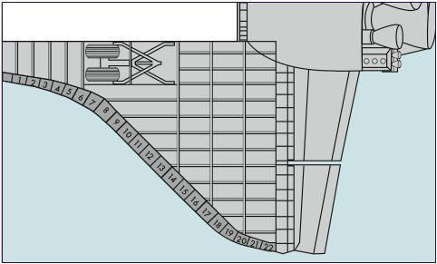
Figure 3.3-1. There are 22 panels of Reinforced Carbon-Carbon on each wing, numbered as shown above.
図3-3-1 : RCCパネルは左右それぞれの主翼に22枚使われています。上にそのナンバーを示します。
Wing Leading Edge Damage
主翼前縁部の損傷
The risk of micrometeoroid or debris damage to the RCC panels has been evaluated several times. Hypervelocity impact testing, using nylon, glass, and aluminum projectiles, as well as low-velocity impact testing with ice, aluminum, steel,and lead projectiles, resulted in the addition of a 0.03 to 0.06-inch-thick layer of Nextel-440 fabric between the Inconel foil and Cerachrome insulation. Analysis of the design change predicts that the Orbiter could survive reentry with a quarter-inch diameter hole in the lower surfaces of RCC panels 8 through 10 or with a one-inch hole in the rest of the RCC panels.
RCCパネルへの微小隕石や破片による損傷のリスクは、これまで何度か検討されてきました。ナイロンやガラス、アルミの射出体を使った高速衝突テストだけでなく、氷やアルミ、鉄、鉛の射出体を使った低速での衝突テストも行われ、0.03〜0.06インチの厚さのNextel-440繊維がインコネルホイルとセラクローム断熱材の間に追加されました。設計変更にともなう分析では、8番から10番のRCCパネルなら直径0.5インチ、それ以外のパネルならば直径1インチの穴が下部に空いた状態でもオービターは大気圏突入が可能だと予測していました。
RCC components have been struck by objects throughout their operational life, but none of these components has been completely penetrated. A sampling of 21 post-flight reports noted 43 hypervelocity impacts, the largest being 0.2 inch. The most significant low-velocity impact was to Atlantis panel 10-right during STS-45 in March andApril 1992. The damaged area was 1.9 inches by 1.6 inches on the exterior surface and 0.5 inches by 0.1 inches in the interior surface. The substrate was exposed and oxidized, and the panel was scrapped. Analysis concluded that the damage was caused by a strike by a man-made object, possibly during ascent. Figures 3.3-2 and 3.3-3 show the damage to the outer and inner surfaces, respectively.
RCCコンポーネントは、そのミッションでの使用の中で何度も物体の衝突を受けてきましたが、完全に突き抜けたものはありませんでした。21回の飛行後レポートをサンプリングした結果、43回の高速での物体衝突が記録されていました。そのうち最大のものは0.2インチです。最も重大な低速衝突は1992年の3月から4月にかけて行われたSTS-45で、アトランティスの左10番パネルに対しての衝突でした。損傷の大きさは、外側の表面で1.9インチ×1.6インチ、内側の面で0.5インチ×0.1インチでした。下地が露出して酸化し、パネルは廃棄されました。その後の分析から、この衝突は人工物によるもので、おそらく上昇中に起きたものであるという結論が出されました。図3-3-2と図3-3-3に外側と内側の損傷の様子をそれぞれ示します。
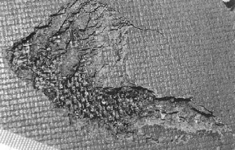
Figure 3.3-2. Damage on the outer surface of RCC panel 10-right from Atlantis after STS-45.
図3-3-2 : STS-45の後、アトランティスの右10番RCCパネルの外側に生じた損傷箇所
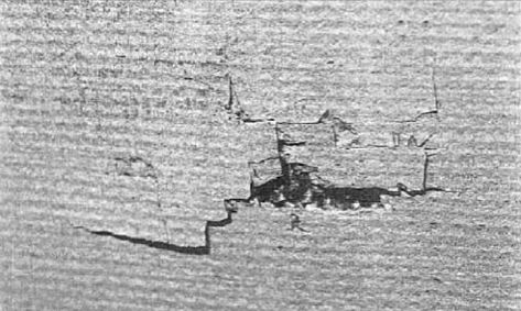
Figure 3.3-3. Damage on the inner surface of RCC panel 10-right from Atlantis after STS-45.
図3-3-2 : STS-45の後、アトランティスの右10番RCCパネルの内側に生じた損傷箇所
Leading Edge Maintenance
主翼前縁部のメンテナンス
Post-flight RCC component inspections for cracks, chips, scratches, pinholes, and abnormal discoloration are primarily visual, with tactile evaluations (pushing with a finger) of some regions. Boeing personnel at the Kennedy Space Center make minor repairs to the silicon carbide coating and surface defects.
フライト後のRCCコンポーネントに対するひび割れや欠け、傷、ピンホール、異常な変色などの検査は主に目視によっておこなわれ、ある部分では触覚(指で押す)が併用されています。また、シリコンカーバイトのコーティングと表面の不具合などの簡単な修理については、ボーイング社の社員がケネディ宇宙センターで行っています。
With the goal of a long service life, panels 6 through 17 are refurbished every 18 missions, and panels 18 and 19 every 36 missions. The remaining panels have no specific refur- bishment requirement.
耐用年数が長いため、6番から17番のパネルは18回のミッション毎に改修され、18番と19番は36回ごとに改修されます。残りのパネルについては交換に関する要件は定められていません。
At the time of STS-107, most of the RCC panels on Columbias left wing were original equipment, but panel 10-left, T-seal 10-left, panel 11-left, and T-seal 11-left had been replaced (along with panel 12 on the right wing). Panel 10-left was tested to destruction after 19 flights. Minor sur- face repairs had been made to panels 5, 7, 10, 11, 12, 13, and 19 and T-seals 3, 11, 12, 13, 14, and 19. Panels and T-seals 6 through 9 and 11 through 17 of the left wing had been refurbished.
STS107においては、コロンビアの左翼に取り付けられたほとんどのRCCパネルは製造当時のものでした。ただし、左10番パネル、左10番T-シール、左11番パネル、左11番T-シールは交換されていました(右翼の12番パネルも同時に交換されています)。10番パネルは19回目のフライト後、テストのために破壊されています。パネル表面の簡単な修理は、5番、7番、10番、11番、12番、13番、19番のパネル、そして3番、11番、12番、13番、14番、19番T-シールに対して行われていました。さらに6番から9番、11番から17番は改修されていました。
Reinforced Carbon-Carbon Mission Life
強化カーボン-カーボンの寿命
The rate of oxidation is the most important variable in de- termining the mission life of RCC components. Oxidation of the carbon substrate results when oxygen penetrates the microscopic pores or fissures of the silicon carbide protec- tive coating. The subsequent loss of mass due to oxidation reduces the load the structure can carry and is the basis for establishing a mission life limit.The oxidation rate is a func- tion of temperature, pressure, time, and the type of heating. Repeated exposure to the Orbiters normal flight environ- ment degrades the protective coating system and accelerates the loss of mass, which weakens components and reduces mission life capability.
酸化の割合は、RCCコンポーネントの寿命を計る上で最も重要な変動要素です。カーボンの素地の酸化は、シリコンカーバイトの保護コーティング上の顕微鏡サイズの細孔やひび割れから酸素が入り込むことでおこります。この酸化によってRCCコンポーネントの質量が失われると、コンポーネントの負荷に対する許容量が少なくなります。これが、コンポーネントの寿命を決めるのです。酸化の度合いは、温度と圧力、時間、加熱のタイプの関数で決まります。オービターの通常のフライト環境でも、それが繰り返されることで保護コーティングシステムの能力を低下させ、コンポーネントの強度を下げて寿命を短くする質量の欠損を引き起こします。
Currently, mass loss of flown RCC components cannot be directly measured. Instead, mass loss and mission life reduc- tion are predicted analytically using a methodology based on mass loss rates experimentally derived in simulated re-entry environments. This approach then uses derived re-entry temperature-time profiles of various portions of RCC components to estimate the actual re-entry mass loss.
今は飛行後のRCCコンポーネントの質量欠損を直接測る方法はありません。その代わりに、RCCコンポーネントの質量欠損と寿命は、再突入時の環境をシミュレーションした実験から得られた質量欠損の割合に従って分析的に予測されています。この手法は、様々なサイズのRCCコンポーネントの時間を追った再突入時の温度変化から、実際の再突入時の質量欠損を概算したものです。
For the first five missions of Columbia, the RCC compo- nents were not coated with Type A sealant, and had shorter mission service lives than the RCC components on the other Orbiters. (Columbias panel 9 has the shortest mis- sion service life of 50 flights as shown in Figure 3.3-4.) The predicted life for panel/T-seals 7 through 16 range from 54 to 97 flights.*7
コロンビアの最初の5回のミッションでは、RCCコンポーネントはタイプAのシーリング材でコーティングされておらず、そのためコロンビアのものは他のオービターのRCCコンポーネントよりも寿命が短くなりました(図3-3-4に示すように、コロンビアの9番パネルはミッション50回分の耐久性しかありませんでした。これは最も短い値です。)7番から16番パネルとT-シールの寿命は54回から97回です。
Localized penetration of the protective coating on RCC components (pinholes) were first discovered on Columbia in 1992, after STS-50, Columbias 12th flight. Pinholes were later found in all Orbiters, and their quantity and size have increased as flights continue. Tests showed that pinholes were caused by zinc oxide contamination from a primer used on the launch pad.
RCCコンポーネントの保護コーティング局所的な浸食(ピンホール)は最初にコロンビアで見つかりました。1992年のSTS-50、コロンビアの12回目のフライトです。ピンホールは後に全てのオービターで発見され、フライト数が増えるに従ってピンホールのサイズと量も大きくなりました。テストによって、ピンホールが発射台で使用されている酸化亜鉛によってできることが分かっています。
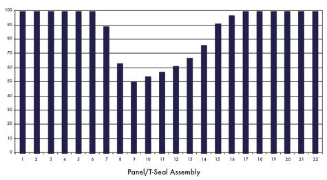
Figure 3.3-4. The expected mission life for each of the wing lead- ing edge RCC panels on Columbia. Note that panel 9 has the shortest life expectancy.
図 3-3-4 : コロンビアの主翼前縁部RCCパネルの期待寿命。9番パネルの寿命が一番短いことに注意。
In October1993,panel12-right was removed from Columbia after its 15th flight for destructive evaluation. Optical and scanning electron microscope examinations of 15 pinholes revealed that a majority occurred along craze cracks in the thick regions of the silicon carbide layer. Pinhole glass chemistry revealed the presence of zinc, silicon, oxygen, and aluminum. There is no zinc in the leading edge sup- port system, but the launch pad corrosion protection system uses an inorganic zinc primer under a coat of paint, and this coat of paint is not always refurbished after a launch. Rain samples from the Rotating Support Structure at Launch Complex 39-A in July 1994 confirmed that rain washed the unprotected primer off the service structure and deposited it on RCC panels while the Orbiter sat on the launch pad. At the request of the Columbia Accident Investigation Board, rain samples were again collected in May 2003. The zinc fallout rate was generally less than previously recorded except for one location, which had the highest rate of zinc fallout of all the samples from both evaluations. Chemical analysis of the most recent rainwater samples determined the percentage of zinc to be consistently around nine per- cent, with that one exception.
1993年10月、コロンビアの右12番パネルが15回目の飛行の後取り外され、破壊検査にまわされました。光学および走査型電子顕微鏡による検査から、シリコンカーバイト層の厚い部分の細かいひび割れにそって15個のピンホールが発見されました。ピンホール部分のガラス繊維の分析から、亜鉛、シリコン、酸素、アルミニウムの存在が確認されました。主翼前縁部の周辺には亜鉛は使用されていません、しかし、発射台の腐食防止のために無機亜鉛の下地材が表面の塗料の下に使用されていました。表面の塗料は必ずしも打ち上げ後に塗り直されるわけでありませんでした。1994年7月に39-A発射台の回転支持架で採取された雨のサンプルに洗い落とされた保護されていない下地剤が含まれ、シャトルが発射台に乗っている間にRCCパネルに成分が蓄積していることが分かりました。コロンビア事故調査委員会の要請により、雨のサンプルは2003年5月にも再び採取されました。亜鉛の落下の率はほとんどがこれまでの記録を下回りましたが、一カ所は前回と今回のサンプル中最も高い率を示していました。その例外的な箇所を除き、直近に行われた雨水のサンプル対する化学分析によると、亜鉛の含有率は9%前後でした。
Specimens with pinholes were fabricated from RCC panel 12-right and arc-jet-tested, but the arc-jet testing did not substantially change the pinhole dimensions or substrate oxidation. (Arc jet testing is done in a wind tunnel with an electrical arc that provides an airflow of up to 2,800 degrees Fahrenheit.) As a result of the pinhole investigation, the sealant refurbishment process was revised to include cleaning the part in a vacuum at 2,000 degrees Fahrenheit to bake out contaminants like zinc oxide and salt, and forcing seal- ant into pinholes.
右12番RCCパネルから取られたピンホールの空いているサンプルに対してアークジェットによるテストが行われましたが、実質ピンホールの形状や下地の酸化はありませんでした。(アークジェットテストは華氏2,800度の風を発生させられる電気アーク装置のついた風洞で行われました) ピンホールに関する調査からシーリング剤の改修プロセスは、酸化亜鉛や塩分を焼き、シーリング材にでピンホールを埋めるために、華氏2000度での吸引によるクリーニングを行うように変更されました。
Post-flight analysis of RCC components confirms that sealant is ablated during each mission, which increases subsurface oxidation and reduces component strength and mission life. Based on the destructive evaluation of Columbias panel 12-right and various arc-jet tests, refurbishment intervals were established to achieve the desired service life.
RCCコンポーネントをフライト後に分析した結果、シーリング材は各フライトの間に溶けていることが分かりました。これが原因で内部の酸化が進み、コンポーネントの強度が下がり寿命が短くなっています。コロンビアの右12番パネル破壊検査と様々なアークジェットテストに基づき、改修のインターバルは本来の寿命を実現できるようなタイミングに定められました。
In November 2001, white residue was discovered on about half the RCC panels on Columbia, Atlantis, and Endeavour. Investigations revealed that the deposits were sodium car- bonate that resulted from the exposure of sealant to rain- water, with three possible outcomes: (1) the deposits are washed off, which decreases sealant effectiveness; (2) the deposits remain on the parts surface, melt on re-entry, and combine with the glass, restoring the sealant composition; or (3) the deposits remain on the parts surface, melt on re- entry, and flow onto metal parts.
2001年11月には、コロンビア、アトランティス、エンデバーのおよそ半分のRCCパネルから白い残留物が発見されました。調査により、この付着物がシーリング材が雨水に曝されたことによって生成された炭酸ナトリウムであることが明らかになりました。この付着物によるシナリオには次の3つが考えられます。(1)付着物が洗い流されシーリング材の効果が低下する。(2) 付着物がパーツ表面に残り、再突入時に溶けてガラスと結合し、シーリング材の組成が復元される。(3) おなじく付着物がパーツ表面に残り、再突入時に溶けて、金属パーツの上に流れる。
The root cause of the white deposits on the surface of RCC parts was the breakdown of the sealant. This does not dam- age RCC material.
RCCパーツの上の白い付着物の根本的な原因はシーリング材の崩壊です。しかし、これはRCC二損傷を与えることはありません。
Non-Destructive Evaluations of Reinforced Carbon- Carbon Components
強化カーボン・カーボンコンポーネントの非破壊検査
Over the 20 years of Space Shuttle operations, RCC has performed extremely well in the harsh environment it is exposed to during a mission. Within the last several years, a few instances of damage to RCC material have resulted in a re-examination of the current visual inspection process. Concerns about potential oxidation between the silicon carbide layer and the substrate and within the substrate has resulted in further efforts to develop improved Non-Destructive Evaluation methods and a better understanding of subsurface oxidation.
スペースシャトルが運用されてきた20年以上に渡って、RCCはミッション中に曝される過酷な環境のもとでその性能を十二分に発揮してきました。最後の数年間を含め、現状の視覚的な検査によって発見されたRCCへのダメージの例はほとんどありませんでした。シリコンカーバイト層と下地材の間、ないし下地材の内部での酸化の可能性を考慮し、より優れた非破壊検査の手法を開発し、さらにRCC内部の酸化についての理解を進めることになりました。
Since 1997, inspections have revealed five instances of RCC silicon carbide layer loss with exposed substrate. In November 1997, Columbia returned from STS-87 with three damaged RCC parts with carbon substrate exposed. Panel 19-right had a 0.04 inch-diameter by 0.035 inch-deep circular dimple, panel 17-right had a 0.1 inch-wide by 0.2 inch- long by 0.025-inch-deep dimple, and the Orbiter forward External Tank attachment point had a 0.2-inch by 0.15-inch by 0.026-inch-deep dimple. In January 2000, after STS-103, Discoverys panel 8-left was scrapped because of similar damage (see Figure 3.3-5).
1997年以来、調査によりRCCのシリコンカーバイト層が脱落し、下地が外部に曝された5つの例が見つかっています。1997年11月、STS-87から帰還したコロンビアの3カ所のRCCパーツが損傷し下地が外部に曝されていました。右19番パネルに直径0.04インチ(約1mm)、深さ0.035インチ(約0.8mm)の窪みが、右17番パネルに幅0.1インチ(約2.5mm)、長さ0.2インチ(約5mm)、深さ0.025インチ(約0.6mm)の窪みが、オービター前部の外部燃料タンク接続部分に0.2インチ(約5mm)×0.15インチ(約4mm)、深さ0.026インチ(約0.6mm)の窪みが空いていました。また、2000年1月には、STS-103の後、ディスカバリーの左8番パネルが同じような損傷があったために廃棄されました(図:3-3-5)。
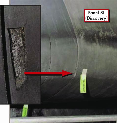
Figure 3.3-5. RCC panel 8-left from Discovery had to be scrapped after STS-103 because of the damage shown here.
Figure 3.3-5. RCC panel 8-left from Discovery had to be scrapped after STS-103 because of the damage shown here.
In April 2001, after STS-102, Columbias panel 10-left had a 0.2-inch by 0.3-inch wide by 0.018-inch-deep dimple in the panel corner next to the T-seal. The dimple was repaired and the panel flew one more mission, then was scrapped because of damage found in the repair.
2001年4月には、STS-102の後、コロンビアの左10番パネルの角、T-シールの隣に0.2インチ(約5mm)×0.3インチ(約7mm)、深さ0.018(約0.45mm)インチの窪みが出来ているのが発見されました。この窪みは修理されこのパネルは次のミッションで使用されましたが、修理箇所に損傷が見つかったため廃棄されました。
Findings:
所見:
F3.3-1
The original design specifications required the RCC components to have essentially no impact resistance.
The original design specifications required the RCC components to have essentially no impact resistance.
F3.3-1
当初の設計仕様では、RCCコンポーネントに対して衝突に対する耐性を要求していない。
当初の設計仕様では、RCCコンポーネントに対して衝突に対する耐性を要求していない。
F3.3-2
Current inspection techniques are not adequate to assess structural integrity of the RCC compo- nents.
Current inspection techniques are not adequate to assess structural integrity of the RCC compo- nents.
F3.3-2
現状の調査方法では、RCCコンポーネントの構造的な状態を適切に評価することは出来ない。
現状の調査方法では、RCCコンポーネントの構造的な状態を適切に評価することは出来ない。
F3.3-3
After manufacturers acceptance non-destructive evaluation, only periodic visual and touch tests are conducted.
After manufacturers acceptance non-destructive evaluation, only periodic visual and touch tests are conducted.
F3.3-3
製造者が納入時におこなう非破壊検査のあとには、視覚と触覚による検査だけが定期的に行なわれる。
製造者が納入時におこなう非破壊検査のあとには、視覚と触覚による検査だけが定期的に行なわれる。
F3.3-4
RCC components are weakened by mass loss caused by oxidation within the substrate, which accumulates with age. The extent of oxidation is not directly measurable, and the resulting mission life reduction is developed analytically.
RCC components are weakened by mass loss caused by oxidation within the substrate, which accumulates with age. The extent of oxidation is not directly measurable, and the resulting mission life reduction is developed analytically.
F3.3-4
RCCコンポーネントは内部の酸化が蓄積され、質量欠損が起きることによって強度が弱くなる。この酸化の範囲は直接測ることができず、コンポーネントの寿命は分析的に予測するしかない。
RCCコンポーネントは内部の酸化が蓄積され、質量欠損が起きることによって強度が弱くなる。この酸化の範囲は直接測ることができず、コンポーネントの寿命は分析的に予測するしかない。
F3.3-5
To date, only two flown RCC panels, having achieved 15 and 19 missions, have been destruc- tively tested to determine actual loss of strength due to oxidation.
To date, only two flown RCC panels, having achieved 15 and 19 missions, have been destruc- tively tested to determine actual loss of strength due to oxidation.
F3.3-5
今のところ、実際の酸化による強度の低下を測るために破壊検査にかけられた実際に飛行に使用されたRCCパネルは2つーそれぞれ15回と19回のフライトを行ったものーしかない。
今のところ、実際の酸化による強度の低下を測るために破壊検査にかけられた実際に飛行に使用されたRCCパネルは2つーそれぞれ15回と19回のフライトを行ったものーしかない。
F3.3-6
Contamination from zinc leaching from a primer under the paint topcoat on the launch pad struc- ture increases the opportunities for localized oxi- dation. Panel 8L (Discovery)
Contamination from zinc leaching from a primer under the paint topcoat on the launch pad struc- ture increases the opportunities for localized oxi- dation. Panel 8L (Discovery)
F3.3-6
発射台の構造物の表面塗装の下の下地材から溶け出した亜鉛によって局所的な酸化の可能性が増えている。左8番パネル(ディスカバリー)
発射台の構造物の表面塗装の下の下地材から溶け出した亜鉛によって局所的な酸化の可能性が増えている。左8番パネル(ディスカバリー)
Recommendation:
勧告 :
R3.3-1
Develop and implement a comprehensive in- spection plan to determine the structural integ- rity of all Reinforced Carbon-Carbon system components. This inspection plan should take advantage of advanced non-destructive inspec- tion technology.
Develop and implement a comprehensive in- spection plan to determine the structural integ- rity of all Reinforced Carbon-Carbon system components. This inspection plan should take advantage of advanced non-destructive inspec- tion technology.
R3.3-1
全ての強化カーボンカーボンシステムコンポーネントの構造的な完全性をチェックする包括的な調査プランを作成実行すること。この調査プランは高度な非破壊検査に重きを置くべきである。
全ての強化カーボンカーボンシステムコンポーネントの構造的な完全性をチェックする包括的な調査プランを作成実行すること。この調査プランは高度な非破壊検査に重きを置くべきである。
R3.3-2
Initiate a program designed to increase the Orbiters ability to sustain minor debris damage by measures such as improved impact-resistant Reinforced Carbon-Carbon and acreage tiles. This program should determine the actual impact resistance of current materials and the effect of likely debris strikes.
Initiate a program designed to increase the Orbiters ability to sustain minor debris damage by measures such as improved impact-resistant Reinforced Carbon-Carbon and acreage tiles. This program should determine the actual impact resistance of current materials and the effect of likely debris strikes.
R3.3-2
対衝撃能力を高めた強化カーボンカーボンとタイルの開発などを通じて、オービターに小さな破片の衝突によるダメージに耐えうる能力を持たせるためのプログラムを開始すること。このプログラムでは起きうる破片の衝突に対する現在使用されている材質の対衝撃性能を実際に測定するべきである。
対衝撃能力を高めた強化カーボンカーボンとタイルの開発などを通じて、オービターに小さな破片の衝突によるダメージに耐えうる能力を持たせるためのプログラムを開始すること。このプログラムでは起きうる破片の衝突に対する現在使用されている材質の対衝撃性能を実際に測定するべきである。
R3.3-3
To the extent possible, increase the Orbiters ability to successfully re-enter the Earths atmosphere with minor leading edge structural sub-system damage.
To the extent possible, increase the Orbiters ability to successfully re-enter the Earths atmosphere with minor leading edge structural sub-system damage.
R3.3-3
可能な範囲で、主翼前縁部の構造に軽微な損傷を抱えたままオービターが大気圏突入を行える能力を強化すること。
可能な範囲で、主翼前縁部の構造に軽微な損傷を抱えたままオービターが大気圏突入を行える能力を強化すること。
R3.3-4
In order to understand the true material character- istics of Reinforced Carbon-Carbon components, develop a comprehensive database of flown Rein- forced Carbon-Carbon material characteristics by destructive testing and evaluation.
In order to understand the true material character- istics of Reinforced Carbon-Carbon components, develop a comprehensive database of flown Rein- forced Carbon-Carbon material characteristics by destructive testing and evaluation.
R3.3-4
強化カーボンカーボンの本当の材料特性を理解するために、実際にフライトに使われた強化カーボンカーボンの材料特性を破壊検査によって明らかにし、そのデータベースを開発すること。
強化カーボンカーボンの本当の材料特性を理解するために、実際にフライトに使われた強化カーボンカーボンの材料特性を破壊検査によって明らかにし、そのデータベースを開発すること。
R3.3-5
Improve the maintenance of launch pad struc- tures to minimize the leaching of zinc primer onto Reinforced Carbon-Carbon components.
Improve the maintenance of launch pad struc- tures to minimize the leaching of zinc primer onto Reinforced Carbon-Carbon components.
R3.3-5
強化カーボンカーボンへの亜鉛下地材の溶出を極力抑えるために発射台の構造部のメンテナンスを向上すること。
強化カーボンカーボンへの亜鉛下地材の溶出を極力抑えるために発射台の構造部のメンテナンスを向上すること。
REINFORCED CARBON-CARBON (RCC)
LEFT WING AND WING LEADING EDGE